
0. Начало
1. Цифровой ввод — кнопка
2. Аналоговый вывод — Fading
3. Аналоговый ввод – потенциометр
Насколько мы помним, у Arduino есть такая замечательная функция — analogRead(), которая считывает значение с указанного аналогового порта.
А это значит мы можем получить простенький осциллограф 🙂
4. Аналоговый ввод – осциллограф
Для этого будем считывать данные с аналогового порта Arduino/Freeduino и записывать их в последовательный (COM) порт. А уже из последовательно порта их будет принимать наша программа и строить график сигнала 🙂
Итак, скетч для Arduino/Freeduino будет совсем простой:
//
// Oscilloscope
//

#define ANALOGA_IN 0

void setup()
{
  Serial.begin(38400); // указываем скорость работы с COM-портом
}

void loop()
{
  int val;
  val = analogRead(ANALOGA_IN); // считываем данные
  Serial.println( val);         // записываем данные в порт
}
Подключившись к порту мы увидим что-то вроде:
403
401
384
361
346
341
341
358
376
386
Осталось только написать программу для превращения данных из последовательного порта в красивый график 🙂
На основе программы построения графиков функций
Graph.pyw (http://purepython.narod.ru/tkinter.html)
я набросал программу для отображения данных из COM-порта.
Для работы потребуется Python и библиотека:
pySerial – собственно сама библиотека для работы с COM-портом (для её работы под Windows требуется pyWin32)
собственно работа с COM-портом из данной библиотеки крайне проста:
#
# для работы с COM-портом нужна библиотека
# pySerial, кроме того, под винду понадобится еще pyWin32
#
import serial
SERIAL_PORT = 'COM1'
SERIAL_SPEED = 38400

ser = serial.Serial(SERIAL_PORT, SERIAL_SPEED)

while 1:
            #s = ser.read()            # считывается один байт
            s = ser.readline().strip() # считывается строка и убираются символы “\r\n”
            print s                    # печатаем на экран
Весь остальной код нужен для работы с графикой Tkinter и отображения линий графика с помощью
create_line(x1,y1,x2,y2,….,xn,yn)
Однако, у меня пока не получилось заставить работать программу в системе real-time –
поэтому бесконечный цикл заменил на конечный
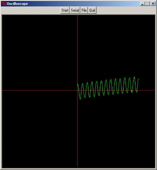
for i in range(0,200):
В итоге, получается, что при нажатии на кнопку «Serial» скрипт считывает 200 значений с COM-порта и строит по ним график:
Другие примеры осциллографов на ардуине:
для проекта Carduino
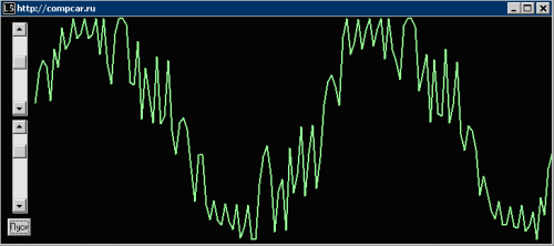
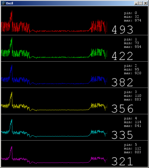
И самый интересный
шестиканальный Arduinoscope на processing 🙂
http://code.google.com/p/arduinoscope/wiki/Usage
Processing является простым скриптовым языком для создания визуализаций с помощью платформы Java Virtual Mashine.
Processing использовался для создания некоторых реклам Nike, клипов Radiohead & R.E.M., инсталляций в музеях, а также входит в учебные курсы некоторых вузов США.
http://processing.org
http://processing.org/download/processing-1.0.5.zip — версия IDE для Windows
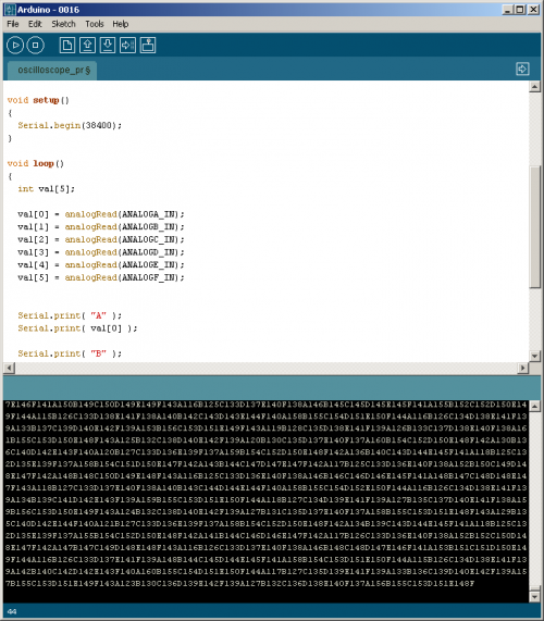
Код скетча для Arduino:
//
// Oscilloscope
// http://accrochages.drone.ws/en/node/90
//

#define ANALOGA_IN 0
#define ANALOGB_IN 1
#define ANALOGC_IN 2
#define ANALOGD_IN 3
#define ANALOGE_IN 4
#define ANALOGF_IN 5

int counter = 0;

void setup()
{
  Serial.begin(38400);
}

void loop()
{
  int val[5];

  val[0] = analogRead(ANALOGA_IN);
  val[1] = analogRead(ANALOGB_IN);
  val[2] = analogRead(ANALOGC_IN);
  val[3] = analogRead(ANALOGD_IN);
  val[4] = analogRead(ANALOGE_IN);
  val[5] = analogRead(ANALOGF_IN);


  Serial.print( "A" );
  Serial.print( val[0] );

  Serial.print( "B" );
  Serial.print( val[1] );
  Serial.print( "C" );
  Serial.print( val[2] );
  Serial.print( "D" );
  Serial.print( val[3] );
  Serial.print( "E" );
  Serial.print( val[4] );
  Serial.print( "F" );
  Serial.print( val[5] );
}
Как видно, сигнал считывается со всех шести аналоговых входов Arduino и сопровождаясь буквенными обозначениями передаётся в последовательный порт.
Подключившись к порту увидим следующее:
A129B131C132D133E134F131A129B131C133D133E134F131A132B134C136D137E138F133
Скетч для Processing-а (как видите IDE – почти такая же :):
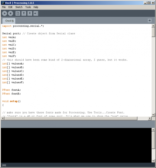
Здесь так же используется функция setup(), а вот вместо loop() используется функция draw()
Сам скетч отличается от авторского только явным указанием последовательного порта:
port = new Serial(this,"COM1", 38400); // Serial.list()[0]
import processing.serial.*;

Serial port; // Create object from Serial class
int valA;
int valB;
int valC;
int valD;
int valE;
int valF;
// this should have been some kind of 2-diminsional array, I guess, but it works.
int[] valuesA;
int[] valuesB;
int[] valuesC;
int[] valuesD;
int[] valuesE;
int[] valuesF;

PFont fontA;
PFont fontB;

void setup()
{

// make sure you have these fonts made for Processing. Use Tools...Create Font.
// "fontA" is a 48 pt font of some sort. It's what we use to show the "now" value.
  fontA = loadFont("CourierNewPSMT-48.vlw");

// "fontB" is a 14 pt font of some sort. It's what we use to show the min and max values.
  fontB = loadFont("CourierNewPSMT-14.vlw");

// I wouldn't change the size if I were you. There are some functions that don't use
// the actual sizes to figure out where to put things. Sorry about that.
  size(550, 600);

// Open the port that the board is connected to and use the same speed
// anything faster than 38.4k seems faster than the ADC on the Arduino can keep up with.
// So, if you want it to be smooth, keep it at or below 38400. 28800 doesn't work at all,
// I do not know why. If you turn on smooth() you need to drop the rate to 19.2k or lower.
// You will probably have to adjust Serial.list()[1] to get your serial port.
  port = new Serial(this,"COM1", 38400); // Serial.list()[0]

// These are 6 arrays for the 6 analog input channels.
// I'm sure it could have just as well been a 2d array, but I'm not that familiar
// with Processing yet and this was the easy way out.
  valuesA = new int[width-150];
  valuesB = new int[width-150];
  valuesC = new int[width-150];
  valuesD = new int[width-150];
  valuesE = new int[width-150];
  valuesF = new int[width-150];
// the -150 gives us room on the side for our text values.

// this turns on anti-aliasing. max bps is about 19.2k.
// uncomment out the next line to turn it on. Personally, I think it's better left off.
//smooth();
}

int getY(int val)
{
  // I added -40 to this line to keep the lines from overlapping, to
  // keep the values within their gray boxes.
  return (int)(val / 1023.0f * (height-40)) - 1;
}

void draw()
{
  String decoder = "";
  while (port.available() >= 3)
  {
    // read serial until we get to an "A".
    decoder = port.readStringUntil(65);
  }
// sanity check. make sure the string we got from the Arduino has all the values inside.
if ((decoder.indexOf("B")>=1) & (decoder.indexOf("C")>=1) &
(decoder.indexOf("D")>=1) & (decoder.indexOf("E")>=1) &
(decoder.indexOf("F")>=1))
{
  // decoder string doesn't contain an A at the beginning. it's at the end.
  valA=int(decoder.substring(0,decoder.indexOf("B")));
  //println("A" + str(valA));
  valB=int(decoder.substring(decoder.indexOf("B")+1,decoder.indexOf("C")));
  //println("B" + str(valB));
  valC=int(decoder.substring(decoder.indexOf("C")+1,decoder.indexOf("D")));
  //println("C" + str(valC));
  valD=int(decoder.substring(decoder.indexOf("D")+1,decoder.indexOf("E")));
  //println("D" + str(valD));
  valE=int(decoder.substring(decoder.indexOf("E")+1,decoder.indexOf("F")));
  //println("E" + str(valE));
  valF=int(decoder.substring(decoder.indexOf("F")+1,decoder.indexOf("A")));
  //println("F" + str(valF));
  }

  //shift the new values into the array, move everything else over by one
  for (int i=0; i
Запустив это приложение увидим красивую картинку :)


Собственно – остаётся:
- научиться определять уровень напряжения сигнала

уровень напряжения можно получить из простой формулы

5V/1024 значений = 0,004883 В/значение (4,883 мВ).
- и определять частоту сигнала :)
NB

Если посмотреть код скетча - увидим, что Arduino работает с COM-портом на скорости 38400 бод (бит/сек http://ru.wikipedia.org/wiki/Бод)

для передачи байта по протоколу RS-232 используется 10 бит (стартовый бит, 8 бит данных, бит чётности (не используется), стоповый бит)

38400/10 = 3840 байт/сек

т.к. на один отсчёт идёт 3 байта (4-5) получаем

3840/3 = 1280 (960-768) отсчётов в секунду
читать далее: 5. Генерация звука – пьезоизлучатель
По теме

Processing и Arduino

Arduino, термины, начало работы

КМБ для начинающих ардуинщиков

Состав стартера (точка входа для начинающих ардуинщиков)
9 комментариев на «“Практическое программирование Arduino/CraftDuino — Аналоговый ввод – осциллограф”»
Установил Processing 1.2, загрузил программу, но появляются ошибки на эту строчку:
port = new Serial(this,’COM1′, 38400); // Serial.list()[0]
пишет: Badly formated character constant
Что бы это значило?
Прежде, чем двигаться дальше, хочу понять как это работает.
в коде скетча была опечатка (одинарные кавычки), а правильно двойные:
Эту проблему решил (вместо одинарных кавычек нужно писать двойные). Проблема другого плана: загружаю скетч в Ардуино и запускаю программу на Питоне. Значение порта считывается. При этом Ардуино больше не может посылать в этот порт какие-либо значения, так как порт занят программой на Питоне.
Может какая фишка есть на Питоне чтобы не занимать порт, а только слушать его?
Ещё вопрос. Запустил программу на Процессинге 1.2. Значения для графика очень долго читаются. В чем причина? (В моём компе, характерной заторможенностью или чем-то ещё)
Прикольно. Оказывается сигнал на порте № 0 (к примеру) влияет на все остальные 5 портов — согласно графикам, полученным программой.
наводки=\
если оч мешает и нужно только как показометр(форму наблюдать а не точные измерения проводить) можно повесить резисторы по 1к на землю.
Должно помочь=)
А теперь мне нужно описание языка программирования, на котором пишутся скечи для Processing, на русском языке.
Не правиьлновыразился. Не языка, а основных функций для работы со строками, портами, графикой, текстом.
называть это «осциллографом» как-то язык не поворачивается. У реальных осциллографов частота семплирования обычно порядка гигасемпл/сек. А это так, рисовалка.