В заметке Практическое программирование Arduino/CraftDuino — Сенсор на светодиоде мы уже показывали, что обычный светодиод можно использовать в качестве простейшего детектора уровня освещённости.
А если взять не один светодиод, а несколько и расположить их рядом друг с другом?
Получим карту освещённости, а значит — своеобразную камеру!
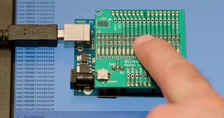
На видео показана работа Arduino Blinkenlight Shield — шилда, первоначально предназначенного для демонстрации световых эффектов.

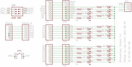
— как видим, шилд — это просто подключение двадцати светодиодов через килоомный резистор ко всем портам Arduino.
идея использования светодиода в качестве датчика состоит в подаче на светодиод обратного напряжения, которое заряжает собственную паразитную ёмкость ножек микроконтроллера и светодиода. Если теперь переключить порт микроконтроллера на вход и отключить внутренний подтягивающий резистор (Z-состояние), то паразитная ёмкость будет разряжаться обратным током светодиода, который зависит от его освещенности.
Измерив время, которое потребовалось для достижения на входе логического нуля, мы можем делать выводы об уровне освещенности светодиода.
Код скетча
//
//	www.blinkenlight.net
//
//	Copyright 2011 Udo Klein
//
//	This program is free software: you can redistribute it and/or modify
//	it under the terms of the GNU General Public License as published by
//	the Free Software Foundation, either version 3 of the License, or
//	(at your option) any later version.
//
//	This program is distributed in the hope that it will be useful,
//	but WITHOUT ANY WARRANTY; without even the implied warranty of
//	MERCHANTABILITY or FITNESS FOR A PARTICULAR PURPOSE. See the
//	GNU General Public License for more details.
//
//	You should have received a copy of the GNU General Public License
//	along with this program. If not, see http://www.gnu.org/licenses/

// Usage
//
// This sketch uses the Blinkenlight Shield as a light
// sensor. In order to make this work jumper the shield
// such the common cathode of the LEDs it connected
// to +5V.
//
// It will output hexadecimal digits that correspond
// to the amount of light captured by the LEDs.
// 0 = very bright light
// higher numbers = less light
//
//
// Theory of operation
//
// For each LED the following happens:

// 1) The PIN is pulled low thus reversing the LED.
//    Thus the LED will act like a capacitor and gets
//    charged.
// 2) We store the current milli second count in
//    start_millis for later use.
// 3) The PIN is put to high Z input and starts to
//    "float" with the voltage of the "LED cap".
// 4) If the LED captures light the "LED cap" will
//    discharge fast, otherwise it discharges slow.
// 5) As the cap discharges the input PIN will
//    float high.
// 6) Once the pin is detected to be high we will
//    compute elapsed_millis by subtracting
//    start_millis from the current milli second
//    count

// The loops are coded in such a way that this
// happens "in parallel". They are also coded
// in such a way that each pin gets some time
// to settle.

// used to store the start milli second count per pin
uint16_t start_millis[20];
// used to store the last computed milli second count when pin floated to high
uint16_t elapsed_millis[20];

uint8_t transform(uint16_t data) {
	// output transformation, used to map uint16_t to 1 hex digit
	// basically a logarithm to the base of 2
	uint8_t i=0;
	while (data) {
		data >>= 1;
		++i;
	}
	return i;
}

boolean pin_is_ok(uint8_t pin) {
	// used to determine which pins are good for light detection
	// pins 0,1 are spoiled by the serial port
	// pin 13 is spoiled by the Arduino's LED
	return (pin != 0) && (pin !=1) && (pin != 13);
}

void setup() {
	Serial.begin(115200);
	Serial.println("go");

	for (uint8_t pin = 0; pin < 20; ++pin) if (pin_is_ok(pin)) {
		pinMode(pin, OUTPUT);
		digitalWrite(pin, LOW);
		start_millis[pin] = millis();
		elapsed_millis[pin] = 0;
	}
	for (uint8_t pin = 0; pin < 20; ++pin) if (pin_is_ok(pin)) {
		pinMode(pin, INPUT);
	}
}

void loop() {
	for (uint8_t pin = 0; pin < 20; ++pin) if (pin_is_ok(pin)) {
		if (digitalRead(pin)) {
			pinMode(pin, OUTPUT);
			elapsed_millis[pin] = millis()-start_millis[pin];
			start_millis[pin] = millis();
			pinMode(pin, INPUT);
		}
	}
	for (uint8_t pin = 0; pin < 20; ++pin) if (pin_is_ok(pin)) {
		Serial.print(transform(elapsed_millis[pin]), HEX);
	}
	Serial.println();
}
Ссылки
Turning LEDs into a camera
Практическое программирование Arduino/CraftDuino - Сенсор на светодиоде
Very Low-Cost Sensing and Communication Using Bidirectional LEDs
По теме
Практическое программирование Arduino - Сенсор на светодиоде
Arduino
Ардуино что это и зачем?
Arduino, термины, начало работы
КМБ для начинающих ардуинщиков
Состав стартера (точка входа для начинающих ардуинщиков)
