
В прошлом году я случайно увидел на ютубе видео, где Richie Hawtin показывает свой домашний сетап, крутит ручки у пульта Allen&Heath XONE и управляет тем самым популярной диджейской программой NI Traktor. Меня очень впечатлило это визуально и технически. До этого я не имел ни малейшего понятия о MIDI протоколе и контроллерах, его использующих.
В то время в ящике стола давно валялась плата Arduino и я все хотел пограться с ней, светодиодом я уже помигал, на LCD экран Hello world! вывел, а какого-нибудь применения в голову не приходило. И тут это видео. В общем я решил сделать свой миди-контроллер. Практической цели особо не было, потому как я не диджей, просто хотелось сделать какое-нибудь устройство с нуля до готового продукта.
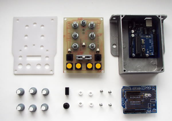
Самым трудным оказалось найти фейдеры. Купить их в городе невозможно, в российских интернет-магазинах какое то гуано, заказывать за рубежом не хотелось из за Почты России с ее молниеносной доставкой. Я уже, в общем то, хотел сделать все вообще без единого движкового резистора, когда коллега подкинул мне пару старых японских резисторов и я все же поставил один как кроссфейдер. Вообще, я почти не тратил деньги на этот проект и большинство деталей обрели вторую жизнь в этом устройстве. Корпус я пару месяцев до этого извлек из помойки на работе, в нем был собран какой то контроллер разряда аккумулятора (вероятно электропогрузчика, вероятно японского потому что там была дюймовая резьба, которую пришлось перенарезать). Мне понравилось что он литой и основательный. По работе мне часто приходится иметь дело с промышленной электроникой, что конечно наложило свой отпечаток и я постарался сделать устройство максимально технологичным в сборке. Я ненавижу шлейфы проводов вырывающиеся из устройства когда ты откручиваешь его крышку,поэтому я решил сделать мезониную конструкцию или этакий бутерброд из плат. Это несколько сложнее чем просто насверлить дырок в корпусе,вставить в них переменных резисторов и соединить все проводами, но зато у меня в корпусе нет ни одного провода и все разбирается-собирается как АК-47.
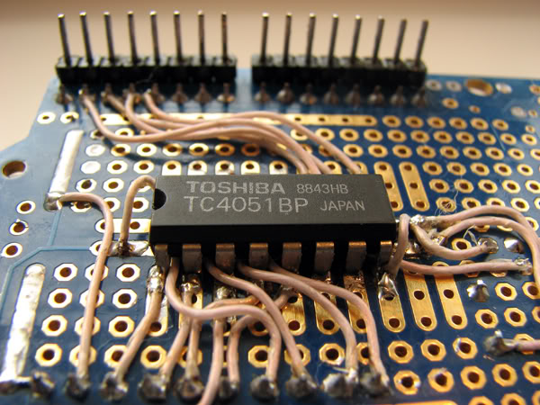
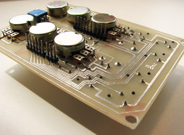
Первая плата в «бутерброде» это стандартный макетный «шилд» (shield) арудуино, на котором я по быстрому распаял аналоговый мультиплексор 4051, который занимается тем что переключает сигнал с каждого потенциометра на один из аналоговых входов ардуино. (всего их 6, а мне надо было минимум 8, поэтому пришлось мультиплексировать).
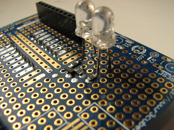
Помимо мультиплексора на плате два светодиода, один из которых индицирует питание через USB, а другой через ключ на транзисторе висит на ноге Tx atmega и мигает при передаче MIDI сообщения.
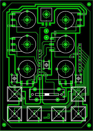
Вторая плата несет на себе все внешние органы управления ( потенциометры и кнопки) и является фальш панелью. Плата разведена в Layout Sprint и напечатана по кустарной ЛУТ технологии.
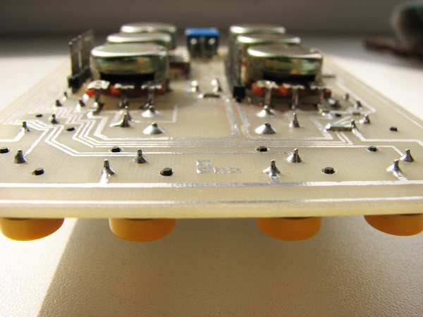
При сборке платы последовательно вставляются друг в друга, последняя закрывает корпус, через 4 фторопластовые шайбы накладывается лиецевая панель из матированного оргстекла и весь «бутерброд» стягивается 4 винтами.
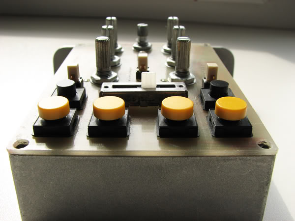
Устройство в сборе выглядит так:
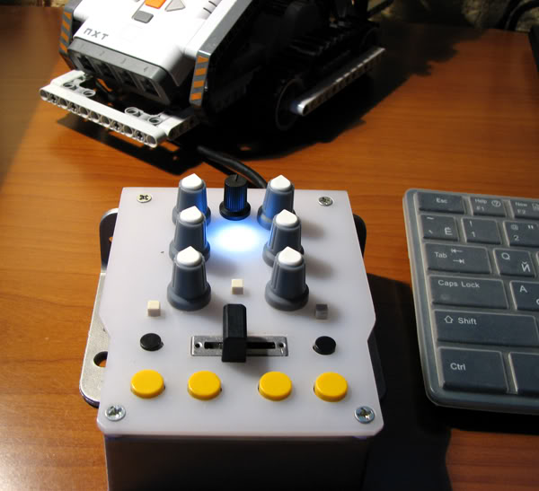
Вероятно это самый маленький диджейский миди контроллер).
Что до софтовой части, то примеров полно на форумах по программированию ардуино и большую часть кода написал умный человек, прекрасно комментируя каждую строчку кода. Вот здесь описание этого проекта.
Я легко переписал его под свои нужды не имея опыта программирования на C, добавив обработку мультиплексора.
#include <TimerOne.h>

// Basic MIDI Controller code for reading all of the Arduino's digital and analogue inputs
// and sending them as MIDI messages to the host PC.
//
// Author: Michael Balzer
// Author#2: 2nz
// Revision History:
// Date        |  Change
// ---------------------------------------------------
// 2011-02-22  |  Initial Release
// 2011-03-30  |  Multiplexing 8 Analogue to pin 0
//
// This work is licensed under a Creative Commons Attribution-NonCommercial-ShareAlike 3.0 Unported License.
// See http://creativecommons.org/licenses/by-nc-sa/3.0/ for license details.

// Uncomment this line to send debug messages to the serial monitor
//#define DEBUG

// MIDI mapping taken from http://www.nortonmusic.com/midi_cc.html
#define MIDI_CC_MODULATION 0x01
#define MIDI_CC_BREATH 0x02
#define MIDI_CC_VOLUME 0x07
#define MIDI_CC_BALANCE 0x08
#define MIDI_CC_PAN 0x0A
#define MIDI_CC_EXPRESSION 0x0B
#define MIDI_CC_EFFECT1 0x0C
#define MIDI_CC_EFFECT2 0x0D

#define MIDI_CC_GENERAL1 0x0E
#define MIDI_CC_GENERAL2 0x0F
#define MIDI_CC_GENERAL3 0x10
#define MIDI_CC_GENERAL4 0x11
#define MIDI_CC_GENERAL5 0x12
#define MIDI_CC_GENERAL6 0x13
#define MIDI_CC_GENERAL7 0x14
#define MIDI_CC_GENERAL8 0x15
#define MIDI_CC_GENERAL9 0x16
#define MIDI_CC_GENERAL10 0x17
#define MIDI_CC_GENERAL11 0x18
#define MIDI_CC_GENERAL12 0x19
#define MIDI_CC_GENERAL13 0x1A
#define MIDI_CC_GENERAL14 0x1B
#define MIDI_CC_GENERAL15 0x1C
#define MIDI_CC_GENERAL16 0x1D
#define MIDI_CC_GENERAL17 0x1E
#define MIDI_CC_GENERAL18 0x1F

#define MIDI_CC_GENERAL1_FINE 0x2E
#define MIDI_CC_GENERAL2_FINE 0x2F
#define MIDI_CC_GENERAL3_FINE 0x30
#define MIDI_CC_GENERAL4_FINE 0x31
#define MIDI_CC_GENERAL5_FINE 0x32
#define MIDI_CC_GENERAL6_FINE 0x33
#define MIDI_CC_GENERAL7_FINE 0x34
#define MIDI_CC_GENERAL8_FINE 0x35
#define MIDI_CC_GENERAL9_FINE 0x36
#define MIDI_CC_GENERAL10_FINE 0x37
#define MIDI_CC_GENERAL11_FINE 0x38
#define MIDI_CC_GENERAL12_FINE 0x39
#define MIDI_CC_GENERAL13_FINE 0x3A
#define MIDI_CC_GENERAL14_FINE 0x3B
#define MIDI_CC_GENERAL15_FINE 0x3C
#define MIDI_CC_GENERAL16_FINE 0x3D
#define MIDI_CC_GENERAL17_FINE 0x3E
#define MIDI_CC_GENERAL18_FINE 0x3F

#define MIDI_CC_SUSTAIN 0x40
#define MIDI_CC_REVERB 0x5B
#define MIDI_CC_CHORUS 0x5D
#define MIDI_CC_CONTROL_OFF 0x79
#define MIDI_CC_NOTES_OFF 0x78


// Comment this line out to disable button debounce logic.
// See http://arduino.cc/en/Tutorial/Debounce what debouncing is used for.
#define DEBOUNCE
// Debounce time length in milliseconds
#define DEBOUNCE_LENGTH 5

// Comment this line out to disable analogue filtering
#define ANALOGUE_FILTER
// A knob or slider movement must initially exceed this value to be recognised as an input. Note that it is
// for a 7-bit MIDI value.
#define FILTER_AMOUNT 5
// Timeout is in microseconds
#define ANALOGUE_INPUT_CHANGE_TIMEOUT 1000000

// Number of digital inputs. Can be anywhere from 0 to 18.
#define NUM_DI 9
// Number of analogue inputs. Can be anywhere from 0 to 6.
//Commented out because of multeplexing to analogue pin0.
//#define NUM_AI 6

// Array containing a mapping of digital pins to channel index. This array size must match NUM_DI above.
byte digitalInputMapping[NUM_DI] = { 5, 6, 7, 8, 9, 10, 11, 12, 13 };
// Array containing a mapping of analogue pins to channel index. This array size must match NUM_AI above.
//Line commented out because of the use multeplexing to the analogue pin0
//byte analogueInputMapping[NUM_AI] = { A0, A1, A2, A3, A4, A5 };

// Contains the current state of the digital inputs.
byte digitalInputs[NUM_DI];
// Contains the current value of the analogue inputs.
byte analogueInputs[8];

// Variable to hold temporary digital reads, used for debounce logic.
byte tempDigitalInput;
// Variable to hold temporary analogue values, used for analogue filtering logic.
byte tempAnalogueInput;

// Preallocate the for loop index so we don't keep reallocating it for every program iteration.
int i = 0;
// Variable to hold difference between current and new analogue input values.
int analogueDiff = 0;
// This is used as a flag to indicate that an analogue input is changing.
boolean analogueInputChanging;

int r0 = 0;      //value of select pin at the 4051 (s0)
int r1 = 0;      //value of select pin at the 4051 (s1)
int r2 = 0;      //value of select pin at the 4051 (s2)

void setup()
{
  // Enable serial I/O at 57600 kbps. This is faster than the standard MIDI rate of 31250 kbps.
  // The PC application which we connect to will automatically take the higher sample rate and send MIDI
  // messages out at the correct rate. We only send things faster in case there is any latency.
  Serial.begin(31250);

  pinMode(2, OUTPUT);    // s0 of 4051
  pinMode(3, OUTPUT);    // s1 of 4051
  pinMode(4, OUTPUT);    // s2 of 4051

  // Initialise each digital input channel.
  for (i = 0; i < NUM_DI; i++)
  {
    // Set the pin direction to input.
    pinMode(digitalInputMapping[i], INPUT);
    // Don't enable pullup resistor on pin 13, as the LED and resistor will always pull it low, meaning the input won't work.
    // Instead an external pulldown resistor must be used on pin 13.
    // NOTE: This will cause all of the high/low logic for pin 13 to be inverted.
    if (digitalInputMapping[i] != 13)
    {
      // Enable the pull-up resistor. This call must come after the above pinMode call.
      digitalWrite(digitalInputMapping[i], HIGH);
    }

    // Initialise the digital state with a read to the input pin.
    digitalInputs[i] = digitalRead(digitalInputMapping[i]);
  }

  // Initialise each analogue input channel.
  // Set the pin 0 direction to input.
    pinMode(0, INPUT);
  for (i = 0; i <=7; i++)
  {
    // multiplexor control
    r0 = i & 0x01;
    r1 = (i>>1) & 0x01;
    r2 = (i>>2) & 0x01;

    digitalWrite(2, r0);
    digitalWrite(3, r1);
    digitalWrite(4, r2);
    // Initialise the analogue value with a read to the input pin.
    analogueInputs[i] = analogRead(0)/8;
  }

  // Assume no analogue inputs are active
  analogueInputChanging = false;

  // This timer runs every 1 second
  Timer1.initialize(ANALOGUE_INPUT_CHANGE_TIMEOUT);
  // When the timer expires, call this function
  Timer1.attachInterrupt(analogueInputStopped);
  // Start the timer
  Timer1.start();

}


void loop()
{
  for (i = 0; i < NUM_DI; i++)
  {
    // Read the current state of the digital input and store it temporarily.
    tempDigitalInput = digitalRead(digitalInputMapping[i]);

    // Check if the last state is different to the current state.
    if (digitalInputs[i] != tempDigitalInput)
    {
      #ifdef DEBOUNCE
      // Wait for a short period of time, and then take a second reading from the input pin.
      delay(DEBOUNCE_LENGTH);
      // If the second reading is the same as the initial reading, assume it must be true.
      if (tempDigitalInput == digitalRead(digitalInputMapping[i]))
      {
      #endif
        // Record the new digital input state.
        digitalInputs[i] = tempDigitalInput;

        // Moved from HIGH to LOW (button pressed)
        if (digitalInputs[i] == 0)
        {
          // All the digital inputs use pullup resistors, except pin 13 so the logic is inverted
          if (digitalInputMapping[i] != 13)
          {
            noteOn(0, 0x00 + i, 0x7F); // Channel 1, middle C, maximum velocity
          }
          else
          {
            noteOff(0, 0x00 + i); // Channel 1, middle C
          }
        }
        // Moved from LOW to HIGH (button released)
        else
        {
          // All the digital inputs use pullup resistors, except pin 13 so the logic is inverted
          if (digitalInputMapping[i] != 13)
          {
            noteOff(0, 0x00 + i); // Channel 1, middle C
          }
          else
          {
            noteOn(0, 0x00 + i, 0x7F); // Channel 1, middle C, maximum velocity
          }
        }
      #ifdef DEBOUNCE
      }
      #endif
    }
  }

  /*
   * Analogue input logic:
   * The Arduino uses a 10-bit (0-1023) analogue to digital converter (ADC) on each of its analogue inputs.
   * The ADC isn't very high resolution, so if a pot is in a position such that the output voltage is 'between'
   * what it can detect (say 2.505V or about 512.5 on a scale of 0-1023) then the value read will constantly
   * fluctuate between two integers (in this case 512 and 513).
   *
   * If we're simply looking for a change in the analogue input value like in the digital case above, then
   * there will be cases where the value is always changing, even though the physical input isn't being moved.
   * This will in turn send out a constant stream of MIDI messages to the connected software which may be problematic.
   *
   * To combat this, we require that the analogue input value must change by a certain threshold amount before
   * we register that it is actually changing. This is good in avoiding a constantly fluctuating value, but has
   * the negative effect of a reduced input resolution. For example if the threshold amount was 2 and we slowly moved
   * a slider through it's full range, we would only detect every second value as a change, in effect reducing the
   * already small 7-bit MIDI value to a 6-bit MIDI value.
   *
   * To get around this problem but still use the threshold logic, a timer is used. Initially the analogue input
   * must exceed the threshold to be detected as an input. Once this occurs, we then read every value coming from the
   * analogue input (not just those exceeding a threshold) giving us full 7-bit resolution. At the same time the
   * timer is started. This timer is used to keep track of whether an input hasn't been moved for a certain time
   * period. If it has been moved, the timer is restarted. If no movement occurs the timer is just left to run. When
   * the timer expires the analogue input is assumed to be no longer moving. Subsequent movements must exceed the
   * threshold amount.
   */
  for (i = 0; i <=7; i++)
  {
    // multiplexor control
    r0 = i & 0x01;
    r1 = (i>>1) & 0x01;
    r2 = (i>>2) & 0x01;

    digitalWrite(2, r0);
    digitalWrite(3, r1);
    digitalWrite(4, r2);

    // Read the analogue input pin 0, dividing it by 8 so the 10-bit ADC value (0-1023) is converted to a 7-bit MIDI value (0-127).
    tempAnalogueInput = analogRead(0) / 8;

    #ifdef ANALOGUE_FILTER
    // Take the absolute value of the difference between the curent and new values
    analogueDiff = abs(tempAnalogueInput - analogueInputs[i]);
    // Only continue if the threshold was exceeded, or the input was already changing
    if ((analogueDiff > 0 && analogueInputChanging == true) || analogueDiff >= FILTER_AMOUNT)
    {
    #else
    if (analogueInputs[i] != tempAnalogueInput)
    {
    #endif
      // If the the analogue input wasn't changing, we need to start the timer again
      if (analogueInputChanging == false)
      {
        Timer1.start();
      }
      // The analogue input was moving, so restart the timer. Only restart it if we're sure the input isn't 'between' a value
      // ie. It's moved more than FILTER_AMOUNT
      else if (analogueDiff >= FILTER_AMOUNT)
      {
        Timer1.restart();
      }

      // The analogue input is moving
      analogueInputChanging = true;

      // Record the new analogue value
      analogueInputs[i] = tempAnalogueInput;

      // Send the analogue value out on the general MIDI CC (see definitions at beginning of this file)
      controlChange(0, MIDI_CC_GENERAL1 + i, analogueInputs[i]);
    }
  }
}

// Send a MIDI note on message
void noteOn(int channel, int pitch, int velocity)
{
  // 0x90 is the first of 16 note on channels
  channel += 0x90;

  // Ensure we're between channels 1 and 16 for a note on message
  if (channel >= 0x90 && channel <= 0x9F)
  {
    #ifdef DEBUG
      Serial.print("Button pressed: ");
      Serial.println(pitch);
    #else
      Serial.print(channel, BYTE);
      Serial.print(pitch, BYTE);
      Serial.print(velocity, BYTE);
    #endif
  }
}

// Send a MIDI note off message
void noteOff(int channel, int pitch)
{
  // 0x80 is the first of 16 note off channels
  channel += 0x80;

  // Ensure we're between channels 1 and 16 for a note off message
  if (channel >= 0x80 && channel <= 0x8F)
  {
    #ifdef DEBUG
      Serial.print("Button released: ");
      Serial.println(pitch);
    #else
      Serial.print(channel, BYTE);
      Serial.print(pitch, BYTE);
      Serial.print(0x00, BYTE);
    #endif
  }
}

// Send a MIDI control change message
void controlChange(int channel, int control, int value)
{
  // 0xB0 is the first of 16 control change channels
  channel += 0xB0;

  // Ensure we're between channels 1 and 16 for a CC message
  if (channel >= 0xB0 && channel <= 0xBF)
  {
    #ifdef DEBUG
      Serial.print(control - MIDI_CC_GENERAL1);
      Serial.print(": ");
      Serial.println(value);
    #else
      Serial.print(channel, BYTE);
      Serial.print(control, BYTE);
      Serial.print(value, BYTE);
    #endif
  }
}

// The timer has expired
void analogueInputStopped()
{
  // Stop the timer so it doesn't repeatedly call this function.
  Timer1.stop();
  // The analogue input is no longer moving
  analogueInputChanging = false;
}
Если опустить детали, то работает это примерно так: При повороте ручки потенциометра меняется напряжение на его среднем выводе ( от 0 до 5 В, что соответствует его крайним положениям), напряжение оцифровывается АЦП и мы получаем байт который преобразуем в формат MIDI сообщения и шлем в последовательный порт, который есть у микроконтроллера для связи с другими цифровыми устройствами. На плате ардуино распаян USB-UART чип FT232 который поднимает виртуальный COM порт на компе. Дальше драйвер древнего синта Rоland который как нельзя кстати создан для работы через COM порт.
И вуаля. Единственная загвоздка это то, что стандартная скорость обмена в MIDI протоколе не стандартна для COM порта, но это быстро пофиксили обитатели форума ардуино, хакнув драйвер FT232.
Необходимо отредактировать файл FTDIPORT.INF
; FTDIPORT.INF
; Copyright (c) 2000-2006 FTDI Ltd.
;
; USB serial port driver installation for Windows 2000 and XP.
;

[Version]
Signature="$Windows NT$"
DriverPackageType=PlugAndPlay
DriverPackageDisplayName=%DESC%
Class=Ports
ClassGUID={4d36e978-e325-11ce-bfc1-08002be10318}
Provider=%FTDI%
CatalogFile=ftdiport.cat
DriverVer=05/19/2006,2.00.00

[SourceDisksNames]
1=%DriversDisk%,,,

[SourceDisksFiles]
ftser2k.sys=1
ftserui2.dll=1
FTLang.Dll = 1
ftcserco.dll = 1

[DestinationDirs]
FtdiPort.NT.Copy=10,system32\drivers
FtdiPort.NT.CopyUI=10,system32
FtdiPort2232.NT.CopyCoInst=10,system32

[ControlFlags]
ExcludeFromSelect=*

[Manufacturer]
%FTDI%=FtdiHw

[FtdiHw]
%VID_0403&PID_6001.DeviceDesc%=FtdiPort232,FTDIBUS\COMPORT&VID_0403&PID_6001
%VID_0403&PID_6010.DeviceDesc%=FtdiPort2232,FTDIBUS\COMPORT&VID_0403&PID_6010

[FtdiPort.NT.AddService]
DisplayName    = %SvcDesc%
ServiceType    = 1                  ; SERVICE_KERNEL_DRIVER
StartType      = 3                  ; SERVICE_DEMAND_START
ErrorControl   = 1                  ; SERVICE_ERROR_NORMAL
ServiceBinary  = %10%\system32\drivers\ftser2k.sys
LoadOrderGroup = Base

; -------------- Serenum Driver install section
[SerEnum_AddService]
DisplayName    = %SerEnum.SvcDesc%
ServiceType    = 1               ; SERVICE_KERNEL_DRIVER
StartType      = 3               ; SERVICE_DEMAND_START
ErrorControl   = 1               ; SERVICE_ERROR_NORMAL
ServiceBinary  = %12%\serenum.sys
LoadOrderGroup = PNP Filter

[FtdiPort.NT.AddReg]
HKR,,EnumPropPages32,,"ftserui2.dll,SerialPortPropPageProvider"

[FtdiPort.NT.Copy]
ftser2k.sys
;serenum.sys

[FtdiPort.NT.CopyUI]
ftserui2.dll
FTLang.dll

[FtdiPort232.NT]
CopyFiles=FtdiPort.NT.Copy,FtdiPort.NT.CopyUI
AddReg=FtdiPort.NT.AddReg

[FtdiPort232.NT.HW]
AddReg=FtdiPort232.NT.HW.AddReg

[FtdiPort232.NT.Services]
AddService = FTSER2K, 0x00000002, FtdiPort.NT.AddService
AddService = Serenum,,SerEnum_AddService
DelService = FTSERIAL

[FtdiPort232.NT.HW.AddReg]
HKR,,"UpperFilters",0x00010000,"serenum"
;HKR,,"ConfigData",1,01,00,3F,3F,10,27,88,13,C4,09,E2,04,71,02,38,41,9c,80,4E,C0,34,00,1A,00,0D,00,06,40,03,80,00,00,d0,80
;HKR,,"ConfigData",1,11,00,3F,3F,10,27,00,00,88,13,00,00,C4,09,00,00,E2,04,00,00,71,02,00,00,38,41,00,00,9C,80,00,00,4E,C0,00,00,34,00,00,00,1A,00,00,00,0D,00,00,00,06,40,00,00,03,80,00,00,00,00,00,00,D0,80,00,00
HKR,,"ConfigData",1,11,00,3F,3F,10,27,00,00,88,13,00,00,C4,09,00,00,E2,04,00,00,71,02,00,00,38,41,00,00,9C,80,00,00,60,00,00,00,34,00,00,00,1A,00,00,00,0D,00,00,00,06,40,00,00,03,80,00,00,00,00,00,00,D0,80,00,00
HKR,,"MinReadTimeout",0x00010001,0
HKR,,"MinWriteTimeout",0x00010001,0
HKR,,"LatencyTimer",0x00010001,16

; -------
; FT2232C
; -------

[FtdiPort2232.NT]
CopyFiles=FtdiPort.NT.Copy,FtdiPort.NT.CopyUI
AddReg=FtdiPort.NT.AddReg

[FtdiPort2232.NT.HW]
AddReg=FtdiPort232.NT.HW.AddReg

[FtdiPort2232.NT.CoInstallers]
AddReg=FtdiPort2232.NT.CoInstallers.AddReg
CopyFiles=FtdiPort2232.NT.CopyCoInst

[FtdiPort2232.NT.Services]
AddService = FTSER2K, 0x00000002, FtdiPort.NT.AddService
AddService = Serenum,,SerEnum_AddService
DelService = FTSERIAL

[FtdiPort2232.NT.CoInstallers.AddReg]
HKR,,CoInstallers32,0x00010000,"ftcserco.Dll,FTCSERCoInstaller"

[FtdiPort2232.NT.CopyCoInst]
ftcserco.dll

;---------------------------------------------------------------;

[Strings]
FTDI="FTDI"
DESC="CDM Driver Package"
DriversDisk="FTDI USB Drivers Disk"
PortsClassName = "Ports (COM & LPT)"
VID_0403&PID_6001.DeviceDesc="USB Serial Port"
VID_0403&PID_6010.DeviceDesc="USB Serial Port"
SvcDesc="USB Serial Port Driver"
SerEnum.SvcDesc="Serenum Filter Driver"
Маководы могут воспользоваться вот этим приложением
Ну и наконец в вашем любимой музыкальной программе любые элементы интерфейса раскидываются на кнопки и крутилки.
Вот небольшое видео в общих чертах демонстрирующее работу контроллера:
0 комментариев на «“MIDI контроллер на Arduino”»
Отличная работа, классное видео!
Отредактировал ссылки(не были видны).
Спасибо)
схему мультиплексора бы, поподробней
где его отредактировать? в системной папке? «C:\Windows\System32\DriverStore\FileRepository\ftdiport.inf_amd64_neutral_9b2b9fd5d576957d\FTDIPORT.INF», он пишет что прав нету на редактирование а также на замену. Как сделать?? win7 64bit
а я например хочу более широкий функционал, пару энкодеров добавить, поболее переменников, ещё есть мысль что бы принимала плата миди и зажигала нужные светодиоды, кто подскажет каким образом?
да и ещё, в этой сборке команды сразу посылаются? без промежуточных программ?
Я использовал роландовский COM драйвер и в тексте это указано. Где и как я его нашел уже и не вспомнить.
Без проблем. Прикручивай что хочешь, хоть энкодеры, хоть любые датчики. Мультиплексируй переменники. По реализации этот проект очень старый. Возможно эта библиотека может облегчить написание своей версии:
https://github.com/FortySevenEffects/arduino_midi_library/
а не поможете с кодом опроса 2х мультиплексоров 74HC4051? я только начал, поэтому для меня сложно пока додумать самому)))
Здравствуйте. Интересует изготовление контроллера под заказ. если возьметесь — напишите мне на почту m26@inbox.ru
Не компилируется в cреде arduino 1.6.2
А под большее кол-во потенциометров и кнопок ее можно допилить. С аппаратной точки зрения проблем нет: ставим 4 мелкосхемки CD4066 и 1 74HC165, после чего аппаратная часть обслужит 32 потенциометра и галетник на 6 позиций. А вот с программной точки как??? Что, где, как в программе надо поправить для работы 4 мультиплексоров и 2 регистров. Дуинку изучать начал недавно, т.ч прошу тапочками не кидаться.
debounce нормально работает? не ощущается задержка на 9й кнопке?
Если не секрет, по какой технологии сделана панель из оргстекла? А особенно прямоугольное отверстие?